


NT5D11 and NT5D14 Lineside T1 Interface cards Page 221 of 894
Circuit Card Description and Installation
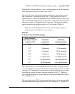
When the Set Alarm command is used, a prompt appears to set the threshold
level and duration period for alarm levels 1 and 2.
The threshold value indicates the number of bit errors detected per second
that is necessary to activate the alarm. The T1 link processes at a rate of
approximately 1.5 mb/s. The threshold value can be set between 3 and 9 and
can be different for each alarm level. Any other value entered will cause the
software to display a “Parameter Invalid” message. The threshold number
entered represents the respective power of 10 as shown in Table 84.
Note: The error rate threshold for a level 2 alarm must be greater (a
smaller power of 10) than for a level 1 alarm.
The duration value is set in seconds and can be set from 1 to 3600 seconds
(1 hour). This duration value indicates how long the alarm will last. Low bit
error rates (10
-7
through 10
-9
)
are restricted to longer durations since it takes
more than one second to detect an alarm condition above 10
-6
. Higher bit
error rates are restricted to shorter durations because the MMI error counter
fills at 65,000 errors.
The alarm indications (LEDs and external alarm contacts) clear automatically
after the duration period has expired, if the Set Clearing (S C) “Enable Self
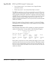
Table 84
T1 bit error rate threshold settings
Alarm threshold
bit errors per second
in power of 10
Threshold
to set alarm
Allowable
duration periods
10
–3
1,500/second 1–21 seconds
10
–4
150/second 1–218 seconds
10
–5
15/second 1–2148 seconds
10
–6
1.5/second 1–3600 seconds
10
–7
1.5/10 seconds 10–3600 seconds
10
–8
1.5/100 seconds 100–3600 seconds
10
–9
1.5/1000 seconds 1000–3600 seconds