


NT5D11 and NT5D14 Lineside T1 Interface cards Page 203 of 894
Circuit Card Description and Installation
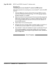
Procedure 11
Connecting to the MDF
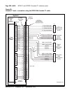
To make the connections at the MDF, follow this procedure:
1 Punch down the first eight pairs of a standard telco 25-pair
female-connectorized cross-connect tail starting with the first tip and ring
pair of the lineside T1 motherboard card slot on the cross-connect side of
the MDF terminals.
2 Plug the NT5D13AA lineside T1 I/O cable into this 25-pair cross-connect
tail at the MDF, regardless of the card slot restrictions that exist from the
vintage level of IPE or CE module used. This connection can also be
made at the MDF without using the NT5D13 lineside T1 I/O cable, by
cross-connecting according to the pinouts in Table 80.
3 Turn over the T1 transmit and receive pairs, where required for hardwiring
the lineside T1 card to local CPE T1 terminal equipment.
End of Procedure
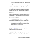
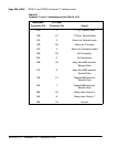
The backplane connector is arranged as an 80-row by 2-column array of pins.
Table 80 shows the I/O pin designations for the backplane connector and the
25-pair Amphenol connector from the I/O panel. Although the connections
from the I/O panel only use 14 of the available 50 pins, the remaining pins are
reserved and cannot be used for other signaling transmissions.
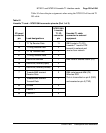
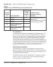
The information in
Table 80 is provided as a reference and diagnostic aid at
the backplane, since the cabling arrangement can vary at the I/O panel. See
Communication Server 1000M and Meridian 1: Large System Installation
and Configuration (553-3021-210) for cable pinout information for the I/O
panel.
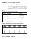
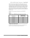
Table 80
Lineside T1 card – backplane pinouts (Part 1 of 2)
Backplane
Connector Pin
I/O Panel
Connector Pin Signal
12A 1 T1 Tip, Receive Data
12B 26 T1 Ring, Receive Data