


Page 210 of 894 NT5D11 and NT5D14 Lineside T1 Interface cards
553-3001-211 Standard 2.00 September 2004
Terminal configuration
For the MMI terminal to be able to communicate to the lineside T1 card, the
interface characteristics must be set to the following:
• Speed – 1200 or 2400 bps, depending on the setting of switch position 1
of Switch 1
• Character width – 8 bits
• Parity bit – none
• Stop bits – one
• Software handshake (XON/XOFF) – off
Software configuration
Although much of the architecture and many of the features of the lineside T1
card differ from the analog line card, the lineside T1 card has been designed
to emulate an analog line card to the CS 1000 Release 4.0 software. Because
of this, the lineside T1 card software configuration is performed the same as
two adjacent analog line cards.
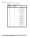
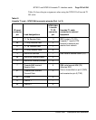
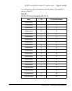
All 24 T1 channels carried by the lineside T1 card are individually configured
using the Analog (500/2500-type) Telephone Administration program
LD 10. Use Table 82 on page 211 to determine the correct unit number and
the NTP Software Input/Output: Administration (553-3001-311) for LD 10
service change instructions.
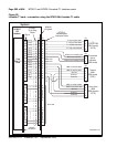
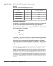
The lineside T1 card circuitry routes 16 units (0-15) on the motherboard and
eight (0-7) units on the daughterboard to 24 T1 channels. The motherboard
circuit card is located in the left card slot, and the daughterboard circuit card
is located in right card slot. For example, if the lineside T1 card is installed
into card slots 0 and 1, the motherboard would reside in card slot 0 and the
daughterboard would reside in card slot 1. In order to configure the terminal
equipment through the switch software, the T1 channel number must be