


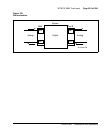


NT8D41AA Serial Data Interface Paddle Board Page 659 of 894
Circuit Card Description and Installation
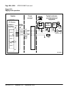
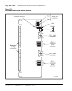
a socket in the CPU area of the backplane allows it to work only when that
CPU is active.
The SDI paddle board is normally installed into a socket in the network area
of the backplane. This allows it to be accessed by either of the system
processors. This is necessary because the active CPU switches automatically
each night at midnight, and whenever a fault occurs on the active CPU card.
The SDI paddle board can also be installed into a socket in the CPU area of
the backplane. This is done when performing maintenance or an upgrade on
the system. The SDI paddle board is plugged into the CPU that is not the
active system CPU. One of the serial ports on the SDI paddle board is then
connected to a maintenance terminal and the CPU board is put into
maintenance mode. Diagnostics can then be run from the maintenance
terminal without having to stop the system. This is also used to perform a
parallel reload of the system software without affecting the operation of the
switch.
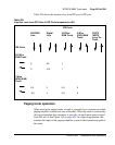
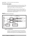
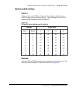
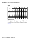
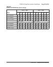
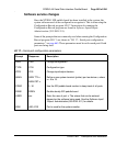
Connector pin assignments
The RS-232-C signals for port 1 are brought out on connector J1 and the
RS-232-C signals for port 2 are brought out on connector J2. The pinouts of
J1 and J2 are identical, so Table 206 can be used for both ports.
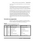
Table 206
Connectors J1 and J2 pin assignments (Part 1 of 2)
Pin # Signal Purpose in DTE mode Purpose in DCE mode
1 CD Carrier detect (Note 1) Carrier detect (Not used)
2 RD Transmitted data Received data
3 TD Received data Transmitted data
4 DTR Data terminal ready Data terminal ready (Note 2)
5 GND Ground Ground
6 DSR Data set ready (Note 1) Data set ready
7 RTS Request to send (Not Used) Request to send (Note 2)