


NT5D97 Dual-port DTI2/PRI2 card Page 309 of 894
Circuit Card Description and Installation
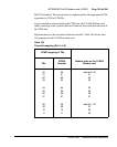
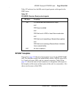
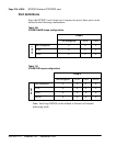
Table 107 indicates how the RR control signal operates with regard to the
DDP2 status.
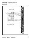
NT5D97 faceplate
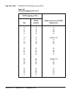
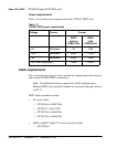
Figure 62 on page 310 illustrates the faceplate layout for the NT5D97 DDP
card. The faceplate contains an enable/disable switch; a DDCH status LED;
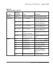
6 x 2 trunk port status LEDs; and six external connectors. Table 108 on
page 311 shows the name of each connector, its designation with respect to
the faceplate and the name and description of the card it is connected to. Also
shown are the names of the LEDs.
Table 107
DCH/MSDL Receiver Ready control signals
RR State Condition
ON D-Channel data rate selected at 64 Kbps
and
PRI2 loop is enabled
and
PRI2 link is not in OOS or Local Alarm mode state
and
PRI2 link is not transmitting a Remote Alarm pattern
and
PRI2 link is not receiving a Remote Alarm Indication
from a remote facility
OFF All other conditions