


Page 770 of 894 NTBK50 2.0 Mb PRI card
553-3001-211 Standard 2.00 September 2004
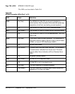
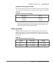
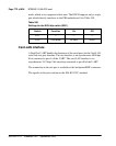
Carrier Shield grounding (Switch SW4)
Table 248 lists the Carrier Shield ground switch settings.
Note: The usual method is to ground the outer conductor of the receive
coax signal.
Receiver functions
The receiver extracts data and clock from an AMI (Alternate Mark Inversion)
coded signal and outputs clock and synchronized data. The receiver is
sensitive to signals over the entire range of cable lengths and requires no
equalization. The clock and data recovery meets or exceeds the jitter
specifications of the CCITT recommendation G.823 and the jitter attenuation
requirements of the CCITT recommendation G.742. This provides jitter
attenuation increasing from 0 dB to 60 dB over the frequency range from
about 6 Hz to 6 KHz.
Transmitter functions
The transmitter takes the binary (dual unipolar) data from the PCM
transceiver and produces bipolar pulses. This conforms to CCITT
recommendation G.703 pulse shape.
Loopbacks
The remote loopback function causes the far-end device to transmit the same
data that it receives, using the jitter attenuated receive clock. The data is
additionally available at the far-end receive data outputs. Local loopback
causes the transmit data and clock to appear at the near-end clock and receive
data outputs. This data is also transmitted on the line unless an Alarm
Indication Signal (AIS) is transmitted instead.
Table 248
Carrier Shield grounding switch settings
Switch Down (On) Up (Off)
SW 4 – 1 Rx – FGND Rx – OPEN
SW 4 – 2 Tx – FGND Tx – OPEN