


QPC513 Enhanced Serial Data Interface card Page 851 of 894
Circuit Card Description and Installation
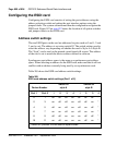
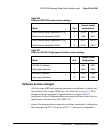
DTE/DCE mode jumper settings
The interface for each ESDI port is configured independently. Ports must be
configured both for electrical interface (RS-232-C or high-speed) and mode
(DTE or DCE). With the proper options set:
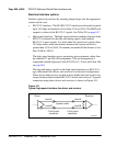
• An ESDI port configured as DTE appears as a terminal to the user
equipment.
• An ESDI port configured as DCE appears as a modem to the user
equipment.
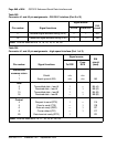
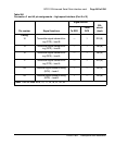
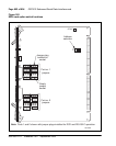
Interface options are set by installing option jumper plugs into the sockets
indicated in Table 266 on page 853 and Table 267 on page 853.
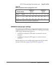
12 13 off on on on on on off *
14 15 on on on on on on on *
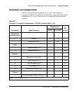
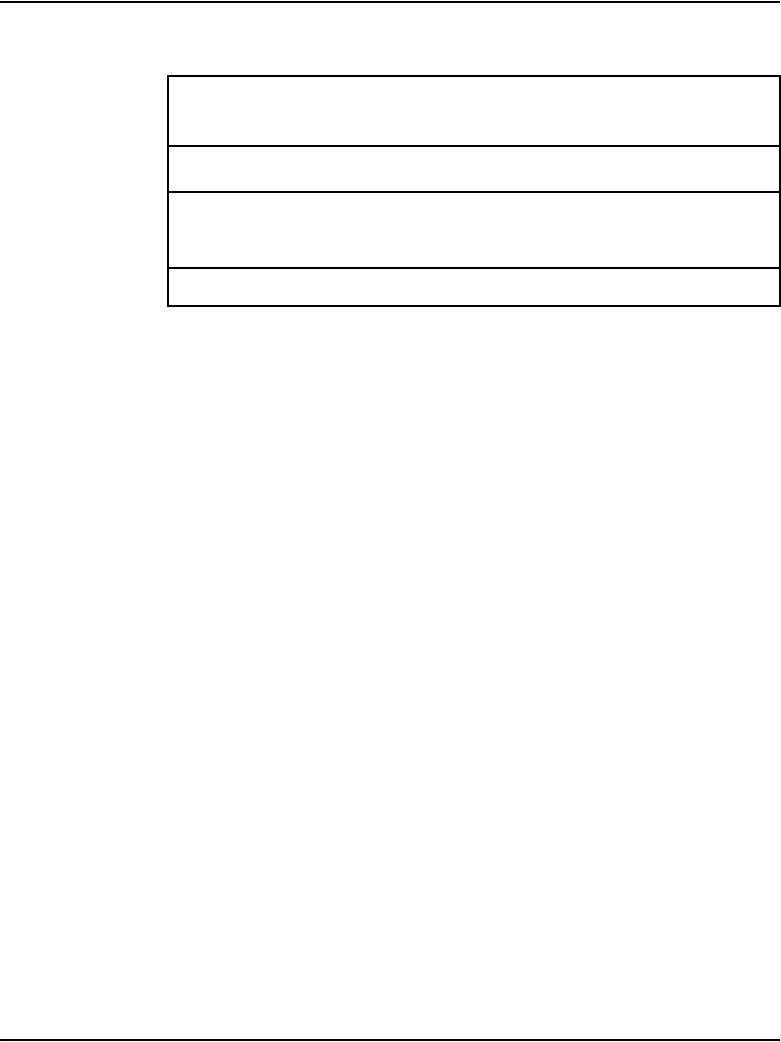
Table 265
ESDI card address switch settings (Part 2 of 2)
Device Number
Switch S2
style A
Switch S2
style B
Port 1Port 212341234
* Switch S2, position 4 is not used on style B cards.