


NT5D33 and NT5D34 Lineside E1 Interface cards Page 267 of 894
Circuit Card Description and Installation
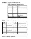
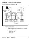
128 LEIs can be linked, located in up to 16 separate IPE shelves, to one MMI
terminal using the daisy chain approach.
If only one LEI is will be installed, cable from the DB9 male connector
labeled “P5” (toward MMI terminal) to one of the COM ports on the back of
any TTY, a PC running a terminal emulation program, or a modem. For
installations of only one card, no connection is made to the DB9 female
connector labeled “P4” (away from MMI terminal).
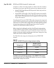
If two or more LEIs are being installed into the system, the MMI port
connections can be daisy-chained together so that only one MMI terminal is
required for up to 128 LEIs. See Figure 42 on page 268. Cards can be located
in up to 15 separate IPE shelves. Start with any card slot in the IPE shelf and
connect to any other card slot. Connected card slots do not need to be
consecutive.
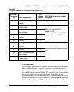
Procedure 13
Connecting two or more LEIs to the MMI terminal
Follow this procedure for connecting two or more LEIs to the MMI terminal:
1 Cable the DB9 male connector labeled “P5” (toward MMI terminal) to one
of the COM ports on the back of any TTY, a PC running a terminal
emulation program, or a modem.
2 Make the connection from the first card to the second card by plugging the
DB9 female connector labeled “P4” (away from MMI terminal) from the
first card into the DB9 male connector of the second card labeled “P5”
(toward MMI terminal).
3 Repeat step 2 for the remaining cards.
4 At the last card of the daisy chain, make no connection from the DB9
female connector labeled “P4” (away from MMI terminal).
5 If two LEIs are too far apart to connect the “P4” and “P5” connectors
connect them with an off-the-shelf DB9 female to DB9 male
straight-through extension cable, available at any PC supply store.
End of Procedure