


Page 284 of 894 NT5D33 and NT5D34 Lineside E1 Interface cards
553-3001-211 Standard 2.00 September 2004
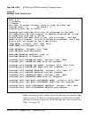
However, responding to this prompt with 2 selects “Table” and allows the
user to set the A/B Bit Mode to whatever configuration the user chooses.
If “Table” is selected, the individual table values will is prompted for. See
Figure 47 on page 285 and Figure 48 on page 286. After each value is
displayed, enter <CR> to do the following:
• accept the current value
• enter just the AB bits (which will be copied to the CD bits)
• enter a complete ABCD bit pattern
• in the case of optional states, a ‘N’ or ‘n’ can be entered to indicate that
the state is not needed
Note that in D4 Framing for E1, there are no CD bits, so they will be ignored.
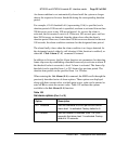
The user is prompted for ABCD bit values for the following states when the
table mode is selected.
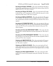
Send and Receive refer to the LEI sending ABCD bits to the CPE (Customer
Provided Equipment) or receiving ABCD bits from the CPE.
Incoming and Outgoing refer to E1 digital link from the CPE point of view.
Incoming is thus an external call arriving over the digital link and accepted
by the CPE. Outgoing is a call originated by the CPE over the digital link.
Configuring the A/B Bit Signaling table is illustrated in Figure 47 and
Figure 48 on page 286.
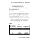
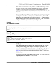
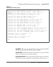
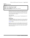
Figure 46
Set Mode (S M): <CR> screen
LEI:>S M
1)
Default
2)
Table
Hit <CR> to accept current value or type in a new one.
Current Mode : 1 New Mode :
Signaling Bits set to Default.
LEI:>