


Page 674 of 894 NT8D41BA Quad Serial Data Interface Paddle Board
553-3001-211 Standard 2.00 September 2004
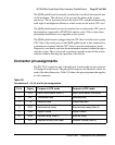
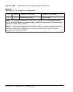
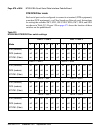
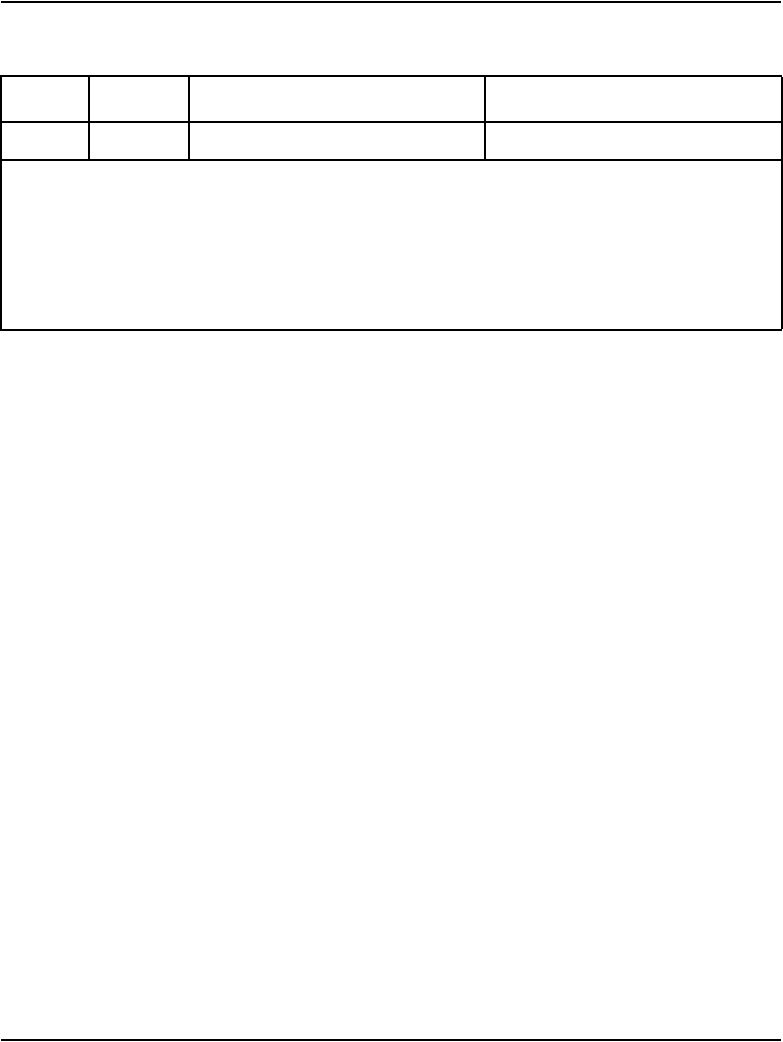
8 CTS Clear to send (Note 1) Clear to send
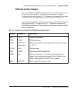
Note 1: In DTE mode the signals CD, DSR, and CTS are tied to +12 volts to signify that the
port on the QSDI paddle board is always ready to transmit and receive data. This mode is set to
connect to a terminal device (DTE).
Note 2: In DCE mode the signals DTR and RTS are tied to +12 volts to signify that the port on
the QSDI paddle board is always ready to transmit and receive data. This mode is set to
connect to a modem device (DCE).
Table 210
Connectors J1, J2, J3, and J4 pin assignments
Pin # Signal Purpose in DTE mode Purpose in DCE mode