


NT5D11 and NT5D14 Lineside T1 Interface cards Page 193 of 894
Circuit Card Description and Installation
Dip switch settings
Begin the installation and configuration of the lineside T1 card by selecting
the proper dip switch settings for the environment. The lineside T1 card
contains two dip switches, each containing eight switch positions. They are
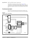
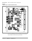
located in the upper right corner of the motherboard circuit card as shown in
Figure 28 on page 194. The settings for these switches are shown in Tables 75
through 78.
When the line-side T1 card is oriented as shown in Figure 28 on page 194, the
dip switches are ON when they are up, and OFF when they are down. The dip
switch settings configure the card for the following parameters:
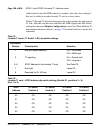
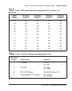
MMI port speed selection
This dip switch setting selects the appropriate baud rate for the terminal or
modem (if any) that is connected to the MMI.
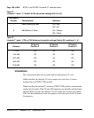
Line Supervisory Signaling protocol
As described in “Lineside T1 call operation” on page 44, the lineside T1 card
is capable of supporting loop start or ground start call processing modes.
Make the selection for this dip switch position based on what type of line
signaling the CPE equipment supports.
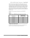
Address of lineside T1 card to the MMI
The address of the lineside T1 card to the MMI is made up of two
components:
• The address of the card within the shelf
• The address of the shelf in which the card resides
These two addresses are combined to create a unique address for the card. The
MMI reads the address of the card within the shelf from the card firmware;
however the address of the shelf must be set by this dip switch.
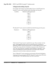
The shelf address dip switch can be from 0 – 15. 16 is the maximum number
of lineside T1 IPE shelves (a maximum of 64 lineside T1 cards) capable of
daisy chaining to a single MMI terminal. For ease, it is recommended that this
address be set the same as the address of the peripheral controller identifier in