


Page 312 of 894 NT5D97 Dual-port DTI2/PRI2 card
553-3001-211 Standard 2.00 September 2004
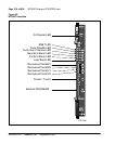
The following sections provide a brief description of each element on the
faceplate.
Enable/Disable Switch
This switch is used to disable the card prior to insertion or removal from the
network shelf. While this switch is in disable position, the card will not
respond to the system CPU.
ENET LEDs
Two red LEDs indicate if the “ENET0” and “ENET1” portions of the card are
disabled. These LEDs are lit in the following cases:
• When the enable/disable switch is in disabled state (lit by hardware).
• After power-up, before the card is enabled.
• When the ENET port on the card is disabled by software.
Trunk Disable (DIS) LEDs
Two red LEDs indicate if the “trunk port 0” or “trunk port 1” portions of the
card are disabled. These LEDs are lit in the following cases:
• Upon reception of the “disable loop” message from the software.
• After power-up.
OOS LEDs
Two yellow LEDs indicate if the “trunk port 0” and “trunk port 1” portions
of the card are out of service.
NEA LEDs
Two yellow LEDs indicate if the near end detects absence of incoming signal
or loss of synchronization in “trunk port 0” or “trunk port 1” respectively. The
near-end alarm causes a far-end alarm signal to be transmitted to the far end.
FEA LEDs
Two yellow LEDs indicate if a far-end alarm has been reported by the far end
(usually in response to a near-end alarm condition at the far end) on “trunk
port 0” or “trunk port 1”.