


Option settings Page 105 of 894
Circuit Card Description and Installation
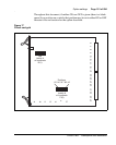
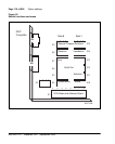
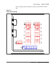
NT5D12AA Dual DTI/PRI (DDP) card
Switch setting tables for this card are listed in subsections according to their
function. Bold font designates factory (default) settings.
General purpose switches
Use switch set SW9 for Trunk 0; use switch set SW15 for Trunk 1
(see Table 14).
Trunk interface switches
A switch provides selection of T1 transmission. Use switch SW4 for Trunk 0;
use switch SW10 for Trunk 1 (see Table 15).
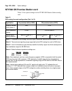
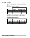
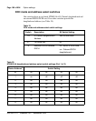
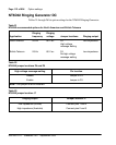
Table 14
General purpose switch settings
Switch Description
SW9/SW15
switch setting
1 Framing Mode off - ESF
on - SF
2 Yellow Alarm Method off - FDL
on - Digit2
3 Zero Code Suppression Mode off - B8ZS
on - AMI
4Unused off
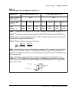
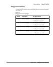
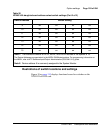
Table 15
Trunk interface transmission mode switch settings
Description SW4/SW10 switch setting
For future use off
T1 on