


NT5D33 and NT5D34 Lineside E1 Interface cards Page 269 of 894
Circuit Card Description and Installation
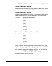
• stop bits – one
• software handshake (XON/XOFF) – off
Software Configuration
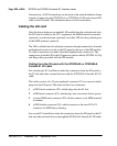
Although much of the architecture and many features of the LEI card are
different from the analog line card, the LEI has been designed to emulate an
analog line card to the CS 1000 Release 4.0 software. Because of this, the LEI
software configuration is the same as for two adjacent analog line cards.
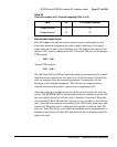
All 30 E1 channels carried by the LEI are individually configured using the
analog (500/2500-type) Telephone Administration program LD 10. Use
Table 99 to determine the correct unit number and Software Input/Output:
Administration (553-3001-311) for LD 10 service-change instructions.
LEI circuitry routes 16 units (0 – 15) on the motherboard and 14 (0 – 13) units
on the daughterboard to 30 E1 channels. The motherboard circuit card is
located in the left card slot, and the daughterboard circuit card is located in
right card slot. For example, if installing the LEI into card slots 0 and 1, the
motherboard would reside in card slot 0 and the daughterboard would reside
in card slot 1. In order to configure the terminal equipment through the switch
software, the E1 channel number will need to be cross-referenced to the
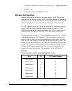
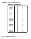
corresponding card unit number. This mapping is shown in Table 99.
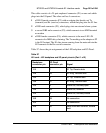
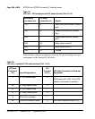
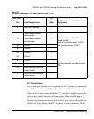
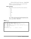
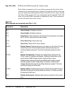
Table 99
Card unit number to E1 channel mapping (Part 1 of 3)
Item TN E1 Channel Number
Motherboard 0 1
Motherboard 1 2
Motherboard 2 3
Motherboard 3 4
Motherboard 4 5
Motherboard 5 6
Motherboard 6 7