


NT5D11 and NT5D14 Lineside T1 Interface cards Page 201 of 894
Circuit Card Description and Installation
Cabling the lineside T1 card
After setting the dip switches and installing the lineside T1 card into the
selected card slots, the lineside T1 card is ready to be cabled to the CPE or
CSU equipment. Connections can also be made to the MMI terminal or
modem (optional), an external alarm (optional), and other lineside T1 cards
for daisy-chain use of the MMI terminal (optional).
The lineside T1 card is cabled from its backplane connector through
connections from the motherboard circuit card only (no cable connections are
made from the daughterboard circuit card) to the input/output (I/O) panel on
the rear of the IPE module. The connections from the lineside T1 card to the
I/O panel are made with the NT8D81AA Tip and Ring cables provided with
the IPE module.
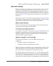
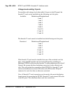
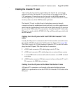
Cabling from the I/O panel with the NT5D13AA lineside T1 I/O
cable
Usually, the I/O panel is connected to the T1 link and other external devices
through the NT5D13AA lineside T1 I/O cable. See Figure 29 on page 202.
This cable consists of a 25-pair amphenol connector (P1) on one end which
plugs into the I/O panel. The other end has 4 connectors:
1 a DB15 male connector (P2) which plugs into the T1 line
2 a DB9 male connector (P3) which plugs into an external alarm system
3 a second DB9 male connector (P5) which connects to an MMI terminal
or modem
4 a DB9 female connector (P4) that connects to the next lineside T1 card’s
P4 connector for MMI daisy chaining
Cabling from the I/O panel at the Main Distribution Frame
All lineside T1 connections can be made at the main distribution frame
(MDF) if it is preferred to not use the NT5D13AA lineside T1 I/O cable at the
I/O panel.