


NTBK50 2.0 Mb PRI card Page 767 of 894
Circuit Card Description and Installation
message format; eight are assigned to voice/data (64 Kbps), one to signaling
(8 Kbps), and one is a data valid bit (8 Kbps).
The incoming serial bit stream is converted to 8-bit parallel bytes to be
directed to padding control. The signaling bits are extracted and inserted by
the A07 signaling interface circuitry. Timeslots 0 and 16 are currently unused
for PCM.
Digital PAD
The software selects A-Law or µ-Law and one of 32 possible PAD values for
each channel. These values are provided in a PROM through which the data
is routed. The idle code for A-Law is 54H and for µ-Law is 7FH. The
unequipped code is FFH for both A-Law and µ-Law.
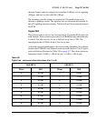
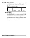
As the idle code and unequipped code can be country dependent, the software
instructs the NTBK50 to use different codes for each direction. The 32 digital
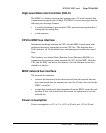
pads available are illustrated in Table 245 on page 767. The values shown are
attenuation levels (1.0dB is 1 dB of loss and –1.0 dB is 1 dB of gain.
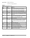
Table 245
Digital Pad - values and offset allocations (Part 1 of 2)
PAD SET 0 PAD SET 1
Offset PAD Offset PAD
0 0.6 dB 0 0.0 dB
1 1.0 dB 1 -1.0 dB
2 2.0 dB 2 -2.0 dB
3 3.0 dB 3 -3.0 dB
4 4.0 dB 4 -4.0 dB
5 5.0 dB 5 -5.0 dB
6 6.1 dB 6 -6.0 dB
7 7.0 dB 7 -7.0 dB
8 8.0 dB 8 -8.0 dB