


Page 264 of 894 NT5D33 and NT5D34 Lineside E1 Interface cards
553-3001-211 Standard 2.00 September 2004
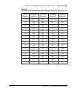
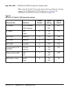
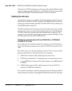
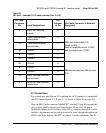
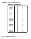
Table 98 shows the pin assignments from the I/O panel relating to the pin
assignments of the lineside E1 I/O cable.
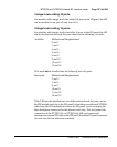
17A 6 Away from MMI terminal, transmit
data
17B 31 Toward MMI terminal, transmit
data
18A 7 Toward MMI terminal, receive
data
18B 32 Daisy chain control 2
19A 8 Daisy chain control 1
19B 33 Ground
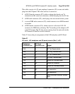
Table 98
LEI card – lineside E1 I/O cable pinouts (Part 1 of 2)
I/O Panel
Connector
Pin
Lead Designations
LEI
Connect
or Pin
LEI Cable Connector to External
Equipment
1 E1 Tip Receive data 11
DB15 male to E1 (P2). LEI is CPE
transmit and receive to network
26 E1 Ring Receive data 3
2 E1 Tip Transmit data 1
27 E1 Ring Transmit data 9
3 Alarm out, common 1
28 Alarm out (normally open) 2 DB9 male to external alarm (P3)
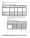
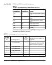
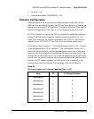
Table 97
LEI card – LEI backplane and I/O panel pinouts (Part 2 of 2)
Backplane
connector pin
I/O Panel
connector pin Signal