


Overview Page 37 of 894
Circuit Card Description and Installation
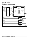
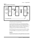
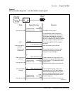
Coder/Decoder circuit
The Coder/Decoder (CODEC) performs Analog to Digital (A/D) and Digital
to Analog (D/A) conversion of the line analog voiceband signal to and from
a digital PCM signal. This signal can be coded and decoded using either the
A-Law or the µ-Law companding algorithm.
On some analog line cards, the decoding algorithm depends of the type of
CODEC installed when the board is built. On others, it is an option selected
using a software overlay.
Variable gain filters
Audio signals received from the analog phone line are passed through a
low-pass A/D monolithic filter that limits the frequency spread of the input
signal to a nominal 200 to 3400 Hz bandwidth. The audio signal is then
applied to the input of the CODEC. Audio signals coming from the CODEC
are passed through a low-pass A/D monolithic filter that integrates the
amplitude modulated pulses coming from the CODEC, and then filters and
amplifies the result. On some of the line cards, the gain of these filters can be
programmed by the system controller. This allows the system to make up for
line losses according to the loss plan.
Balancing network
Depending on the card type, the balancing network provides a 600 ¾, 900 ¾,
3COM or 3CM2 impedance matching network. It also converts the 2-wire
transmission path (tip and ring) to a 4-wire transmission path (Rx/ground and
Tx/ground). The balancing network is usually a transformer/analog (hybrid)
circuit combination, but can also be a monolithic Subscriber Line Interface
Circuit (SLIC) on the newer line cards.
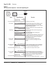
Line interface and foreign voltage protection
The line interface unit connects the balancing network to the telephone tip
and ring pairs. The off-premise line card (NT1R20) has circuitry that protects
the line card from foreign voltage surges caused by accidental power line
connections and lightning surges. This protection is necessary if the
telephone line leaves the building where the switch is installed.
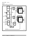
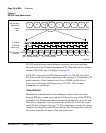
The line interface unit has a relay that applies the ringing voltage onto the
phone line. See Figure 4 on page 36. The RSYNC signal from the 20 Hz