


Page 710 of 894 NTAK10 2.0 Mb DTI card
553-3001-211 Standard 2.00 September 2004
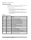
Physical description
The 2 Mb DTI pack uses a standard 9.5" by 12.5", multi-layer printed circuit
board. The faceplate is 7/8” wide and contains six LEDs.
The LEDs operate as follows:
• After the card is plugged in, the LEDs (a-e) are turned on by the
power-up circuit. The clock controller LED is independently controlled
by its own microprocessor.
• After initialization, the LEDs (a-e) flash three times (0.5 seconds on,
0.5 seconds off) and then individual LEDs will go into appropriate states,
as shown in Table 229.
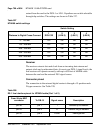
Table 229
NTAK10 LED states (Part 1 of 2)
LED State Definition
DIS On (Red) The NTAK10 circuit card is disabled.
Off The NTAK10 is not in a disabled state.
OOS On (Yellow) The NTAK10 is in an out-of-service state.
Off The NTAK10 is not in an out-of-service state.
NEA On (Yellow) A near end alarm state has been detected.
Off No near end alarm.
FEA On (Yellow) A far end alarm state has been detected.
Off No far end alarm.
LBK On (Yellow) NTAK10 is in loop-back mode.
Off NTAK10 is not in loop-back mode.
CC On (Red) The clock controller is switched on and disabled.
On (Green) The clock controller is switched on and is either locked to a
reference or is in free-run mode.