


NT8D15 E&M Trunk card Page 625 of 894
Circuit Card Description and Installation
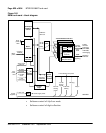
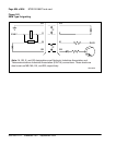
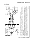
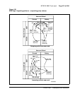
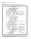
Figure 143
4-wire DX signaling
Tip B
T1
J3
J5
T2 (Note 2)
Ring B
a
b
Tip A
Ring A
a
b
Distant circuit
electromechanical (may also be
Succession 1000M, Succession
1000, or Meridian 1)
Local system circuit
Ð48V
Ð48V
4
8
553-AAA1151
1100Ω
(Note 1)
K1
R
C
R
eq
130Ω
130Ω
K1
R
State of
trunk
detector
130Ω
600Ω
1.21kΩ
(Note 4)
1.21kΩ
R
C
R
B
R
A
R
F
750Ω
400Ω600Ω
370Ω 370Ω
370Ω
250Ω
See Note 5
See
Note 5
6µF 4µF
4µF
Balancing
resistance
(see Note 3)
370Ω
1kΩ
R
A
or
D1
B1
A1
R
E
External
loop
(5kΩ max.)
See
Note 5
Note 1:
The equivalent bridge circuit resistance as seen from distant trunk during the signaling is 1250 ±125 Ohms.
Note 2:
T1 and T2 resistance is 47 Ohms for 600 Ohm termination option.
Note 3:
Compute total balancing resistance as follows (note that in some new DX circuits, a 1260 Ohm resistor is permanently wired in series
with the selectable resistance). Total balancing R = external loop resistance + 0.5 x T1 resistance + 0.5 x T2 resistance + [(R
A
+ R
D
) if not shorte
d
out] + R
eq
. Resistance of transformers at electromechanical end is low and can be ignored. "External loop resistance" is defined as 1/2 the loop
resistance of one cable pair.
Note 4:
If the external loop is >2500 Ohms, the loop adjustment resistors R
A
and R
B
are shorted out. If the external loop is <2500 Ohms, R
A
an
d
R
B
are in the circuit.
When the system is connected to another Meridian 1 or pulse and external loop resistance is <2500 Ohms, the loop
adjustment resistors must be shorted in one machine. If the external loop is >2500 Ohms, the loop adjustment resistors must be shorted out in
both machines.
Note 5:
When the system is connected to an electromechanical trunk using 4-wire operation, a 4µF capacitor must be connected from the A1 to
B1 lead at each end of the trunk. (These may already be installed.) It is also recommended that a 6µF capacitor be connected in series with the
balancing resistance.
Ð48V