


NTAK10 2.0 Mb DTI card Page 713 of 894
Circuit Card Description and Installation
10 bits in a 10 message format; eight are assigned to voice/data (64 Kbps),
one to signaling (8 Kbps), and one is a data valid bit (8 Kbps).
Transmit data
To transmit data on the carrier, the incoming serial bit stream from the
NTAK02 circuit card is converted to 8-bit parallel bytes. The signaling bits
are extracted by the signaling interface circuitry.
Digital Pad: The parallel data is presented to the pad PROM. The PROM
contains pad values, idle code, and A/µ-law conversion. They can be set
independently for incoming and outgoing voice on a per channel basis. Four
conversion formats are provided: A-law to A-law, A-law to µ-law, µ-law to
A-law, µ-law to µ-law.
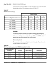
Each of these four formats has up to 32 unique pad values. The NTAK10 card
provides the pad values of -10, -9, -8, -7, -6,-5, -4, -3, -2, -1, 0, 0.6, 1, 2, 3, 4,
5, 6, 7, 8, 9, 10, 11, 12, 13, and 14 dB (also idle and unassigned code). A
negative pad is a positive gain.
The pad PROM output is converted from parallel to serial format and passed
on to a multiplexer, which passes PCM/data, TS0, and TS16 information. The
FAS pattern is sent in even TS0s, while in odd TS0s alarm information is sent.
The multiplexer output is fed to the carrier interface which can forward it to
the carrier or perform per channel loopback.
Receive data
To receive data, PCM/Data from the carrier interface is converted from serial
to parallel, is buffered, and is fed to the pad prom. It then sent onto the
DS-30X interface, where signaling information from the signaling interface
circuitry is multiplexed.
DS-30X microprocessor
The DS-30X is a utility processor, responsible for the following tasks:
• controlling the DS-30X interface
• receiving and decoding of messages and taking appropriate action
• transmitting TS16 messages to the TS16 microprocessor