


Page 514 of 894 NT7D16 Data Access card
553-3001-211 Standard 2.00 September 2004
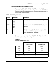
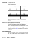
Be sure to re-label the MDF to show that the module has been upgraded to
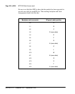
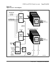
provide one cable for each IPE slot. The resulting backplane and cable
arrangement should look like this:
Backplane slot-connector I/O panel cable position
L0 A
L1 B
L2 C
L3 D (new cable)
L4 E
L5 F
L6 G
L7 H (new cable)
L8 K
L9 L
L10 M
L11 N (new cable)
L12 R
L13 S
L14 T
L15 U (new cable)