


NT5D97 Dual-port DTI2/PRI2 card Page 313 of 894
Circuit Card Description and Installation
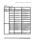
LBK LEDs
Two yellow LEDs indicate if a remote loopback test is being performed on
trunk port 0 or trunk port 1. The loopback indication is active when the digital
trunk is in remote loopback mode. Normal call processing is inhibited during
the remote loopback test.
DCH LED
When the dual colored LED is red, it indicates the on-board DDCH is present
but disabled. When the dual colored LED is green, it indicates the on-board
DDCH is present and enabled. If a DDCH is not configured on the DDP2
card, this lamp is not lit.
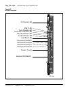
Unit 0 Clk Connectors
Two RJ11 connectors for connecting:
• Digital trunk unit 0 recovered clock to primary or secondary reference
source on clock controller card 0.
• Digital trunk unit 0 recovered clock to primary or secondary reference
source on clock controller card 1.
Unit 1 Clk Connectors
Two RJ11 connectors for connecting:
• Digital trunk unit 1 recovered clock to primary or secondary reference
source on clock controller card 0.
• Digital trunk unit 1 recovered clock to primary or secondary reference
source on clock controller card 1.
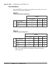
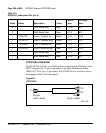
Connector J5 (TRK)
A 9 pin D-Type connector used to connect:
• Digital trunk unit 0 receive and transmit Tip / Ring pairs.
• Digital trunk unit 1 receive and transmit Tip / Ring pairs.
Connector J6 (DCH)
A 26 pin D-type connector is used to connect the DDP2 card to the external
MSDL or D-channel handler.