


Page 150 of 894 Option settings
553-3001-211 Standard 2.00 September 2004
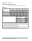
QPC775 Clock Controller card
Tables 57 and 58 give option settings for the QPC775 Clock Controller
card.
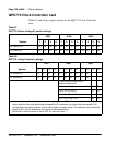
Table 57
QPC775 (before vintage E) switch settings
System
SW2 SW3 SW4
1 2 3 4 1 2 3 4 1 2 3 4
CS 1000M MG off off off off off off off off on on on on
CS 1000M SG on on on on off off off off on on on on
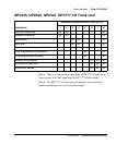
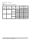
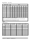
Table 58
QPC775 vintage E switch settings
System
SW1 SW2 SW4
1 2 3 4 1 2 3 4 1 2 3 4
CS 1000M SG on on on on off off off off off on * *
CS 1000M MG on off off off off off off off ** on * *
*Cable length between the J3
faceplate connectors:
0–4.3 m (0–14 ft) off off
4.6–6.1 m (15–20 ft) off on
6.4–10.1 m (21–33 ft) on off
10.4–15.2 m (34–50 ft) on on
* If there is only one Clock Controller card in the system, set to OFF. If there are two Clock Controller
cards, determine the total cable length between the J3 connectors (no single cable can exceed 25 ft.)
and set these two switch positions for this cable length, as shown above. The maximum total (combined)
length is 50 ft. Set the switches on both cards to the same settings.
** Set to ON for clock controller 0. Set to OFF for clock controller 1.