


NT7D16 Data Access card Page 505 of 894
Circuit Card Description and Installation
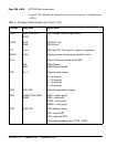
Configuring the Data Access card
LD 11 must be configured to accept the DAC. The commands listed here
must be answered. LD 20 prints out card information when requested. For a
complete list of the service change prompts and responses, see Software
Input/Output: Administration (553-3001-311).
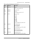
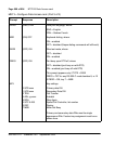
DAC administration (LD 11)
Responding R232 or R422 to the TYPE prompt in LD11 begins the prompt
sequence for the DAC configuration. Responses to the following prompts are
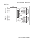
22R 22 O-V GND5 7 SDB5 Connector
23T 48 V-G DCD5 8 3
23R 23 G-V DSR5 6
24T 49 V-BR RI5 22
24R 24 BR-V CTS5 5
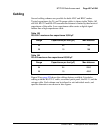
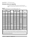
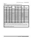
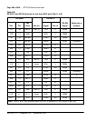
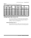
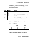
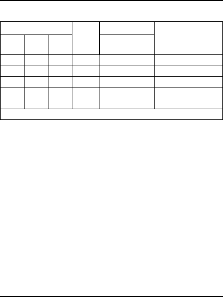
Table 166
RS-232-C and RS-422 pinouts for last three DAC ports (Part 2 of 2)
I/O cable
Unit no.
RS-232-C
RS-422
Signal
Patch pair or
octopus
Pair Pin
Pair
color
Signal Pin no.
Note: Units 4 and 5 are available when the DAC is installed in a fully wired 24-pair slot.