


NT5D33 and NT5D34 Lineside E1 Interface cards Page 251 of 894
Circuit Card Description and Installation
Installation and Configuration
Installation and configuration of the LEI consists of six basic steps:
1 Set the dip switches on the LEI for the call environment.
2 Install the LEI into the selected card slots.
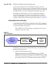
3 Cable from the I/O panel to the LTU, MMI terminal or modem
(optional), external alarm (optional), and other LEIs for daisy chaining
use of MMI terminal (optional).
4 Configure the MMI terminal.
5 Configure the LEI through the CS 1000 Release 4.0 software and verify
self-test results.
6 Verify initial E1 operation and configure MMI (optional).
Steps 1-5 are explained in this section. Step 6 is covered in “Man-Machine E1
maintenance interface software” on page 272.
Installation and configuration of the ELEI follows the same steps. If enhanced
functionality is required, then one additional step is required:
7 The Meridian 1 line unit(s) associated with the lineside E1 must be
programmed for wireless operation (set WTYP=DECT, and WRLS=Yes
in LD 10) in non–concentrated mode. Refer to Software Input/Output:
Administration (553-3001-311) details on LD 10.
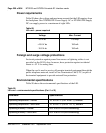
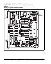
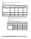
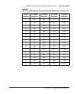
Dip switch settings
Begin the installation and configuration of the LEI by selecting the proper dip
switch settings for the environment. The LEI contains two dip switches, each
containing eight switch positions. They are located in the upper right corner
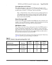
Storage temperature –50° to + 70° C (–58° to 158° F), ambient
Storage humidity 5% to 95% RH (non-condensing)
Table 90
LEI card – environmental specifications (Part 2 of 2)
Parameter Specifications