


NT5D11 and NT5D14 Lineside T1 Interface cards Page 195 of 894
Circuit Card Description and Installation
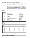
T1 framing
The lineside T1 card is capable of interfacing with CPE or CSU equipment
either in D4 or ESF framing mode. Make the selection for this dip switch
position based on what type of framing the CPE or CSU equipment supports.
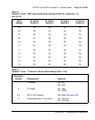
T1 coding
The lineside T1 card is capable of interfacing with CPE or CSU equipment
using either AMI or B8ZS coding. Make the selection for this dip switch
position based on what type of coding the CPE or CSU equipment supports.
DSX-1 length
Estimate the distance between the lineside T1 card and the hardwired local
CPE, or the Telco demarc RJ48, for the carrier facility connecting the lineside
T1 and the remote CPE. Make the selection for this dip switch position based
on this distance.
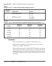
Line supervision on T1 failure
This setting determines in what state all 24 ports of the lineside T1 card
appears to the CS 1000S, CS 1000M, and Meridian 1 in case of T1 failure.
Ports can appear as either in the on-hook or off-hook states on T1 failure.
Note: All idle lineside T1 lines will go off-hook and seize a Digitone
Receiver when the off-hook line processing is invoked on T1 failure.
This may prevent DID trunks from receiving incoming calls until the
lineside T1 lines time-out and release the DTRs.
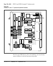
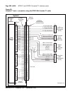
Daisy-chaining to MMI
If two or more lineside T1 cards are installed and the MMI is used,
daisy-chain the cards together to use one MMI terminal or modem, See
Figure 30 on page 209. Make the selection for this dip switch position based
on how many lineside T1 cards will be installed.
MMI master or slave
This setting is used only if daisy-chaining the cards to the MMI terminal or
modem. This setting determines whether this card is a master or a slave in the
MMI daisy-chain. Select the master setting if this card is the card that is