


Page 602 of 894 NT8D14 Universal Trunk card
553-3001-211 Standard 2.00 September 2004
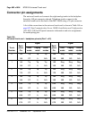
Connector pin assignments
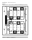
The universal trunk card connects the eight analog trunks to the backplane
through a 160-pin connector shroud. Telephone trunks connect to the
universal trunk card at the back of the MG 1000S using a 25-pin connector.
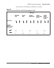
A list of the connections to the universal trunk card is shown in Table 184 on
page 602. See Communication Server 1000S: Installation and Configuration
(553-3031-210) for I/O panel connector information and wire assignments
for each tip/ring pair.
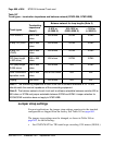
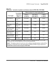
Table 184
Universal trunk card – backplane pinouts (Part 1 of 2)
Trunk
Number
Back-
plane
Pin
Signal
Back-
plane
Pin
Signal
RAN
mode
Paging
mode
Other
modes
RAN
mode
Paging
mode
Other
modes
0 12A Tip Tip Tip 12B Ring Ring Ring
13A CP A N/A 13B MB RG N/A
1 14A Tip Tip Tip 14B Ring Ring Ring
15A CP A N/A 15B MB RG N/A
2 16A Tip Tip Tip 16B Ring Ring Ring
17A CP A N/A 17B MB RG N/A
3 18A Tip Tip Tip 18B Ring Ring Ring
19A CP A N/A 19B MB RG N/A
4 62A Tip Tip Tip 62B Ring Ring Ring
63A CP A N/A 63B MB RG N/A
5 64A Tip Tip Tip 64B Ring Ring Ring
65A CP A N/A 65B MB RG N/A
6 66A Tip Tip Tip 66B Ring Ring Ring
67A CP A N/A 67B MB RG N/A