


Option settings Page 147 of 894
Circuit Card Description and Installation
QPC551 Radio Paging Trunk card
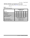
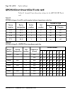
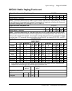
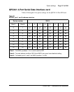
Signal duration on the 18-pair faceplate S1 (F33)
1 2 3 4 5 6
Binary value (.1 second) 1 2 4 8 16 32
Note: This switch determines the length of time a signal stays on the 18-pair data bus. The time
is set in binary to the nearest tenth second. For example, to keep data on the bus for 5 seconds,
the switch settings total 50 by closing S1.2, S1.5, and S1.6.
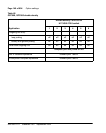
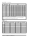
Signal duration and pause time S2 (G33)
1 2 3 4 5 6 7
Binary value (.1 second) 1 2 4 8 16 32 64
Note: This switch determines the time data must stay on the 18-pair data bus plus the pause
time between the removal of data and the reappearance of subsequent data. The time is set in
binary to the nearest tenth second. For example, to keep data on the bus for 5 seconds and have
a pause time of 3.2 seconds, the switch settings should total 82 by closing S2.2, S2.5, and S2.7.
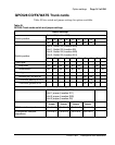
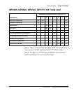
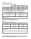
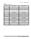
Application S3 (E2) S4 (F2)
Unit 0, Unit 1
1 2 Address 3 4 5 6 Address 3 4 5 6
Paging 0 off off off off 8 off off off on
single on 1 on off off off 9 on off off on
multiple off 2 off on off off 10 off on off on
3 on on off off 11 on on off on
Timer* 4 on off on off 12 on off on on
enabled on 5 on on on off 13 on off on on
disabled off 6 off on on off 14 off on on on
7 on on on off 15 on on on on
* When enabled, this switch prevents a signal from being sent from a paging unit until 5 seconds have
elapsed since the beginning of the previous signal on that same unit.
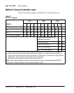
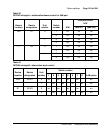
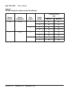
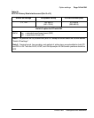
S5 (E38)
Unit 0
S6 (D1)
Unit 1
Impedance termination 1
Real on
Complex off