


NT8D15 E&M Trunk card Page 653 of 894
Circuit Card Description and Installation
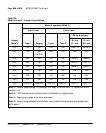
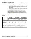
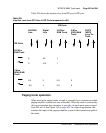
Table 205 shows the insertion loss from IPE port to IPE port.
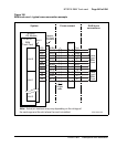
Paging trunk operation
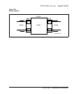
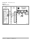
When used in the paging mode, a trunk is connected to a customer-provided
paging amplifier system (not zone selectable). When the trunk is accessed by
dial-up or attendant-key operation, it provides a loop closure across control
leads PG and A. See Figure 153 on page 654. In a typical application, this
transfers the input of the paging amplifier system to the transmission path of
the trunk.
Table 205
Insertion Loss from IPE Ports to IPE Ports (measured in dB)
IPE Ports
IPE Ports
500/2500
Line
Digital
Line
2/4 Wire
E&M Trunk
4 Wire
(ESN) E&M
Trunk
CO/FX
/WATS
Loop Tie
Trunk
2/4 Wire
E&M Trunk
6
3
3.5
-0.5
1
1
4 Wire
(ESN) E&M
Trunk
5.5
2.5
3
-1
0.5
0.5
0
0