


NT1R20 Off-Premise Station Analog Line card Page 173 of 894
Circuit Card Description and Installation
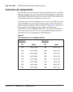
Before the appropriate balance network can be selected, the loop length
between the near-end and the far-end station must be known. To assist in
determining loop length, “Port-to-port loss” on page 178 describes some
typical resistance and loss values for the most common cable lengths for
comparison with values obtained from actual measurements.
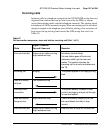
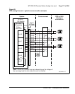
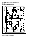
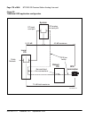
Application
Off-premise station application
The NT1R20 OPS analog line card is designed primarily to provide an
interface for off-premise station lines. An OPS line serves a terminal – usually
a telephone – remote from the PBX either within the same serving area as the
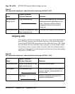
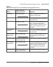
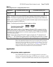
Gain treatment
(Note 5)
No Ye s
Note 1: Configured in the Analog (500/2500-type) Telephone Administration program LD 10.
Note 2: The maximum signaling range supported by the OPS analog line card is 2300 ohms.
Note 3: Loss of untreated (no gain devices) metallic line facility. Upper loss limits correspond to
loop resistance ranges for 26 AWG wire.
Note 4: The following are the default software impedance settings:
ONP CLS OPX CLS
Termination Impedance (TIMP): 600 ohms 600 ohms
Balanced Impedance (BIMP): 600 ohms 3CM2
Note 5: Gain treatment, such as a Voice Frequency Repeater (VFR) is required to limit the
actual OPS loop loss to 4.5 dB, maximum. VFR treatment of metallic loops having untreated
loss greater than 15 dB (equivalent to a maximum signaling range of 2300 ohms on 26 AWG
wire) is not recommended.
Note 6: Jumper strap settings JX.0 and JX.1 apply to all eight units; “X” indicates the unit
number, 0 – 7. “Off” indicates that a jumper strap is not installed across both pins on a jumper
block. Store unused straps on the OPS analog line card by installing them on a single jumper.
Table 70
OPS analog line card – configuration (Part 2 of 2)
Application On-premise station (ONS) Off-premise station (OPS)