


Page 660 of 894 NT8D41AA Serial Data Interface Paddle Board
553-3001-211 Standard 2.00 September 2004
Configuring the SDI paddle board
Configuring the SDI paddle board consists of setting these option switches for
each serial port:
• Port address
• Baud rate
• DTE/DCE/Fiber mode
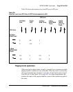
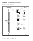
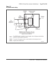
The SDI paddle board has seven option switches, SW 2–8. Figure 156 on
page 664 identifies the location of option switches on the SDI paddle board.
Instructions for setting these switches are in the section that follows.
Once the board has been installed, the system software must be configured to
recognize it. Instructions for doing this are found in “Software service
changes” on page 665”.
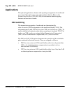
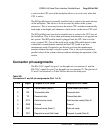
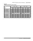
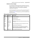
8 CTS Clear to send (Note 1) Clear to send
Note 1: In DTE mode the signals CD, DSR, and CTS are tied to +12 volts to signify that the port
on the SDI paddle board is always ready to transmit and receive data.
Note 2: In DCE mode the signals DTR and RTS are tied to +12 volts to signify that the port on
the SDI paddle board is always ready to transmit and receive data.
Table 206
Connectors J1 and J2 pin assignments (Part 2 of 2)
Pin # Signal Purpose in DTE mode Purpose in DCE mode