


Page 252 of 894 NT5D33 and NT5D34 Lineside E1 Interface cards
553-3001-211 Standard 2.00 September 2004
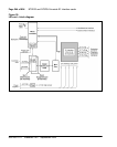
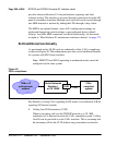
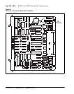
of the motherboard circuit card as shown in Figure 41 on page 254. The
settings for these switches are shown in Table 91 on page 255 through
Table 94 on page 258.
When the LEI card is oriented as shown in Figure 41 on page 254, the dip
switches are ON when they are up, and OFF when they are down. The dip
switch settings configure the card for the following parameters:
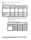
MMI port speed selection
This dip switch setting selects the appropriate baud rate for the terminal or
modem (if any) that is connected to the MMI.
Line Supervisory Signaling protocol
The LEI is capable of supporting loop start or ground start call processing
modes. Make the selection for this dip switch position based on what type of
line signaling the Customer Premise Equipment (CPE) supports.
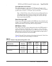
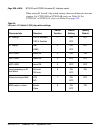
Address of LEI to the MMI
The address of the LEI to the MMI is made up of two components:
• the address of the card within the shelf
• the address of the shelf in which the card resides
These two addresses are combined to create a unique address for the card. The
MMI reads the address of the card within the shelf from the card firmware;
the address of the shelf must be set by this dip switch.
The shelf address dip switch can be from 0 to 15, 16 being the maximum
number of lineside E1 IPE shelves (a maximum of 64 LEI cards) capable of
daisy chaining to a single MMI terminal. For ease, it is recommended that this
address be set the same as the address of the peripheral controller identifier in
LD 97 for type: XPE. However, this is not mandatory, and, since the dip
switch is limited to 16, this will not always be possible.
E1 framing
The LEI is capable of interfacing with LTU equipment either in CRC-4 or
FAS only framing mode. Make the selection for this dip switch position based
on what type of framing the LTU equipment supports.