


NT5D33 and NT5D34 Lineside E1 Interface cards Page 279 of 894
Circuit Card Description and Installation
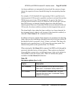
— an alarm message is created in the alarm log and the MMI terminal
— the LEI card enters line-conditioning mode
— a yellow alarm message is sent to the CPE/LTU
Line processing sends the CS 1000S, CS 1000M, and Meridian 1 either all
“on-hook” or all “off-hook” signals, depending on the dip switch setting of
the card. See Table 94 on page 258.
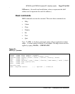
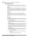
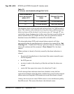
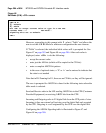
When the Set Alarm command is selected, the prompt appears for setting
the threshold level and duration for alarm levels 1 and 2.
The E1 link processes at a rate of approximately 2.0 mb/s. The threshold
value indicates the ratio of the total number of bits that must be detected as
being in error per second before the LEI activates an alarm. It can be set
between 3 and 9 and can be different for each alarm level. Any other value
entered will cause the MMI to display a “Parameter Invalid”
message. The digit entered as the threshold value is a number representing a
negative power of 10 as shown in Table 101.
Note: The error-rate threshold for a level 2 alarm must be greater (a
smaller power of 10) than for a level 1 alarm. Remember that the
numbers being represented are negative numbers. Since 3 represents –3,
and 4 represents –4, 4 represents a smaller number than 3 does.
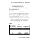
Table 101
E1 bit error rate threshold settings (Part 1 of 2)
Alarm threshold bit
errors per second in
power of 10
Threshold to set
alarm
Allowable Duration
Periods
10
-3
2,000/ second 1-21 seconds
10
-4
200/second 1-218 seconds
10
-5
20/second 1-2148 seconds
10
-6
2.0/second 1-3600 seconds
10
-7
2.0/10 seconds 10-3600 seconds