


Page 206 of 894 NT5D11 and NT5D14 Lineside T1 Interface cards
553-3001-211 Standard 2.00 September 2004
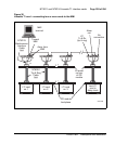
T1 connections
T1 signaling for all 24 channels is transmitted over P2 connector pins 1, 3, 9,
and 11 as shown in Table 81 on page 205. Plug the DB15 male connector
labeled “P2” into the T1 link. T1 transmit and receive pairs must be turned
over between the lineside T1 card and CPE equipment that is hardwired
without carrier facilities. If the lineside T1 card is connected through T1
carrier facilities, the transmit and receive pairs must be wired straight through
to the RJ48 at the Telco demarc, the CSU, or other T1 carrier equipment. The
T1 CPE equipment at the far end will also have transmit and receive wired
straight from the RJ48 demarc at the far end of the carrier facility.
External alarm connections
P3 connector pins 3, 4, and 28 can be plugged into any external alarm
hardware. Plug the male DB9 connector labeled “P3” into the external alarm.
These connections are optional, and the functionality of the lineside T1 card
is not affected if they are not made.
The MMI (described in detail in “Man-Machine T1 maintenance interface
software” on page 213) monitors the T1 link for specified performance
criteria and reports on problems detected.
33 Ground 5 DB9 female away from MMI (P4)
Wired as DTE
Data is transmitted on pin 2 (TXD)
and received on pin 3 (RXD)
8 Control 1 7
32 Control 2 9
30 Away from MMI terminal
Transmit Data
3
6 Away from MMI terminal
Receive Data
2
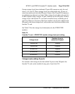
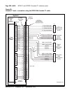
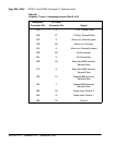
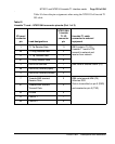
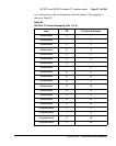
Table 81
Lineside T1 card – NT5D13AA connector pinouts (Part 2 of 2)
I/O panel
connector
pin
Lead designations
NT5D13AA
Lineside
T1 I/O
connector
pin
Lineside T1 cable
connector to external
equipment