


Page 256 of 894 NT5D33 and NT5D34 Lineside E1 Interface cards
553-3001-211 Standard 2.00 September 2004
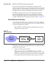
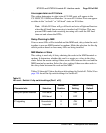
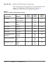
When dip switch #1, positions 2 and 8 are set to “Table,” AB Bits are
configured by the user through the Set Mode MMI command (see “Set Mode”
on page 283). Otherwise, the signaling scheme selected by dip switch 1,
positions 2 and 8 will be used.
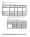
IPE Shelf address for LEI See Table 93 3
4
5
6
See Table 93 OFF
OFF
OFF
OFF
Card type for ringer
allocation
XTI = 19
XMLC = 18
7
7
ON
OFF
OFF
E1 signaling See Table 92 8 OFF OFF
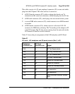
Table 92
LEI card – signaling-type dip switch settings
Switch #1
Characteristic Selection Position 2 Position 8
Signaling Type Loop start OFF OFF
Ground start ON OFF
Australian P2 OFF ON
Table ON ON
Table 91
LEI card – Switch #1 dip switch settings (Part 2 of 2)
Characteristic Selection
Switch
Position
Switch
Setting
Factory
Default