


Page 186 of 894 NT5D11 and NT5D14 Lineside T1 Interface cards
553-3001-211 Standard 2.00 September 2004
“Man-Machine T1 maintenance interface software” on page 213 for
information on T1 link maintenance. If the card detects that tests are being run
or that alarms have been disabled through the MMI, this LED will light and
will remain lit until these conditions are no longer detected, then it will turn
off.
Functional description
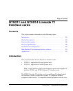
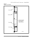
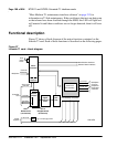
Figure 27 shows a block diagram of the major functions contained on the
lineside T1 card. Each of these functions is described on the following pages.
Figure 27
Lineside T1 card – block diagram
Micro-
controller
Tx PCM
Async card
LAN link
Front
panel
LEDs
Card LAN
interface
T1 Interface
(One for all
24 channels)
Line interface unit power
Rx PCM
Controller
card
Digital
Gain/Loss
Pads
Slot 1
Motherboard
(16 channels)
Slot 2
Daughterboard
(8 channels)
Mux
Seq.
Reg
553-6476
Power
supplies
+8.5 V dc
+5 V dc logic power
T1 Tx Tip
Man/Machine Interface
External Alarm Interface
T1 Tx Ring
T1 Rx Tip
T1 Rx Ring
Backplane
Common
Peripheral
Equipment
connector
Card slot
addresses
Backplane
DS-30X
interface