


Overview Page 47 of 894
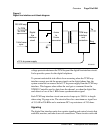
Circuit Card Description and Installation
Call operation will be described by categorizing the operation into the
following main states:
• Idle (on-hook)
• Incoming calls
• Outgoing calls
• Calls disconnected by the CO
• Calls disconnected by the telephone
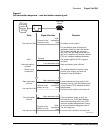
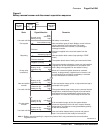
Loop Start Mode
In Loop Start mode , the A and B bits have the following meaning:
Transmit from LTI:A bit = 0 (tip ground on)
B bit = Ringing (0=on, 1=off)
Receive to LTI: A bit = Loop (0=open, 1=closed)
B bit = 1 (no ring ground)
When a T1 channel is idle, the lineside T1 card simulates a ground on the tip
lead and –48Vdc on the ring lead to the terminal equipment by setting its
transmit A bit to 0 and transmit B bit to 1. Accordingly, an on-hook channel
on the terminal equipment simulates an open loop toward the lineside T1
card, causing the lineside T1 card’s receive bits to be set to A = 0 and receive
B = 1.
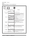
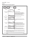
Incoming calls
Incoming calls to terminal equipment attached to the lineside T1 card can
originate either from stations that are local (served by the PBX), or remote
(served through the PSTN). To provide the ringing signal to a telephone the
lineside T1 card simulates an additional 90V on the ring lead to the terminal
equipment by alternating the transmit B bit between 0 and 1 (0 during ring on,
1 during ring off). When an incoming call is answered by the terminal
equipment going off-hook, the terminal equipment simulates tripping the
ringing and shutting off ringing, causing the lineside T1 card’s receive A bit
to be changed from 0 to 1.