


Page 816 of 894 NTRB21 DTI/PRI/DCH TMDI card
553-3001-211 Standard 2.00 September 2004
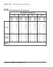
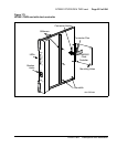
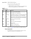
In general, the first five LEDs operate as follows:
• During system power up, the LEDs are on.
• When the self-test is in progress, the LEDs flash on and off three times,
then go into their appropriate states, as shown in Table 257.
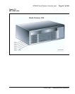
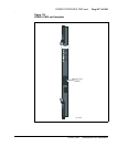
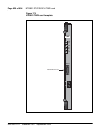
Figure 174 on page 817 shows the faceplate of the NTRB21 TMDI card.
Power requirements
The DTI/PRI obtains its power from the backplane, and draws less than
2 amps on +5 V, 50 mA on +12 V, and 50 mA on –12 V.
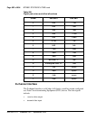
Table 257
NTRB21 LED states
LED State Definition
DIS On (Red) The NTRB21 circuit card is disabled.
Off The NTRB21 is not in a disabled state.
ACT On (Green) The NTRB21 circuit card is in an active state. No alarm states
exist, the card is not disabled, nor is it in a loopback state.
Off An alarm state or loopback state exists, or the card has been
disabled. See the other faceplate LEDs for more information.
RED On (Red) A red-alarm state has been detected.
Off No red alarm.
YEL On (Yellow) A yellow alarm state has been detected.
Off No yellow alarm.
LBK On (Green) NTRB21 is in loop-back mode.
Off NTRB21 is not in loop-back mode.