


NT8D15 E&M Trunk card Page 619 of 894
Circuit Card Description and Installation
Functional description
The NT8D15 E&M Trunk card serves various transmission requirements.
The trunk circuits on the card can operate in either A-Law or µ-Law
companding modes. The mode of operation is set by service change entries.
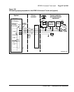
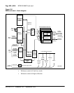
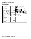
Figure 140 on page 620 shows a block diagram of the major functions
contained on the E&M trunk card. Each of these functions is discussed on the
following pages.
Common features
The following features are common to all circuits on the NT8D15 E&M
Trunk card:
• Analog-to-digital and digital-to-analog conversion of transmission
signals.
• Interfaces each of the four PCM signals to one DS30X timeslot in A10
format.
• Transmit and receive SSD signaling messages over a DS30X signaling
channel in A10 format.
• Ability to enable and disable individual ports or the entire card under
software control.
• Provides outpulsing on the card. Make break ratios are defined in
software and down loaded at power up and by software commands.
• Provides indication of card status from self-test diagnostics on faceplate
Light Emitting Diode (LED).
• Supports loopback of PCM signals to DS30X for diagnostic purposes.
• Card ID provided for auto configuration and determining serial number
and firmware level of card.
• Software controlled terminating impedance (600, 900, or 1200 ohm) two
and four-wire modes.
• Allows trunk type to be configured on a per port basis in software.
• Software controlled 600 ohm balance impedance is provided.
• Isolation of foreign potentials from transmission and signaling circuit.