


Page 182 of 894 NT5D11 and NT5D14 Lineside T1 Interface cards
553-3001-211 Standard 2.00 September 2004
mail systems, channel banks containing FXS cards, and key systems such as
the Nortel Networks Norstar. The lineside T1 card differs from trunk T1 cards
in that it supports terminal equipment features such as hookflash, transfer,
hold, and conference.
This card occupies two card slots in the main or expansion cabinets. The
lineside T1 card can be installed in the system’s main cabinet or one of the
expansion cabinets (there are no limitations on the number of cards that can
be installed in the Cabinet system).
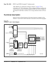
The lineside T1 card emulates an analog line card to the system software;
therefore, each channel is independently configurable by software control in
LD 10. The lineside T1 card also comes equipped with a Man-Machine
Interface (MMI) maintenance program. This feature provides diagnostic
information regarding the status of the T1 link.
Physical description
The lineside T1 card mounts into any two consecutive IPE slots. The card
consists of a motherboard and a daughterboard. The motherboard circuitry is
contained on a standard 31.75 by 25.40 cm. (12.5 by 10.0 in) printed circuit
board. The daughterboard is contained on a 5.08 by 15.24 cm (2.0 by 6.0 in)
printed circuit board and mounts to the motherboard on six standoffs.
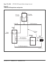
Card connections
The lineside T1 card uses the NT8D81AA Tip and Ring cable to connect from
the IPE backplane to the 25-pair amphenol connector on the IPE I/O input/
output (I/O) panel. The I/O panel connector then connects directly to a T1
line, external alarm, and an MMI terminal or modem using the NT5D13AA
lineside T1 I/O cable available from Nortel Networks.
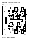
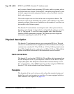
Faceplate
The faceplate of the card is twice as wide as the other standard analog and
digital line cards, and occupies two card slots. It comes equipped with four
LED indicators. See Figure 26 on page 183.