


Page 242 of 894 NT5D33 and NT5D34 Lineside E1 Interface cards
553-3001-211 Standard 2.00 September 2004
The LEDs give status indications on the operations as described in Table 87.
The STATUS LED indicates if the LEI has successfully passed its self test,
and therefore, if it is functional. When the card is installed, this LED remains
lit for two to five seconds as the self-test runs. If the self-test completes
successfully, the LED flashes three times and remains lit. When the card is
configured and enabled in software, the LED goes out. If the LED continually
flashes or remains weakly lit, replace the card.
The STATUS LED indicates the enabled/disabled status of both card slots of
the LEI simultaneously. To properly enable the card, both the motherboard
and the daughterboard slots must be enabled. The STATUS LED will turn off
as soon as either one of the LEI slots have been enabled. No LED operation
will be observed when the second card slot is enabled. To properly disable the
card, both card slots must be disabled. The LED will not turn on until both
card slots have been disabled.
The RED ALARM LED indicates if the LEI has detected an alarm condition
from the E1 link. Alarm conditions can include such conditions as not
receiving a signal, the signal has exceeded bit error thresholds or frame slip
thresholds. See “Man-Machine E1 maintenance interface software” on
page 272 for information on E1 link maintenance.
If one of these alarm conditions is detected, this LED will light. Yellow alarm
indication is sent to the far end as long as the near end remains in a red alarm
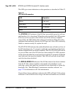
Table 87
LEI card LED operation
LED Operation
Status Line card
Red alarm E1 near end
Yellow alarm E1 far end
Maint Maintenance