


NT5D97 Dual-port DTI2/PRI2 card Page 329 of 894
Circuit Card Description and Installation
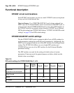
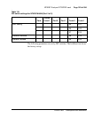
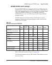
The following parameters are set by DIP switches. The boldface font shows
the factory set-up.
LBO Setting S5 S11
S6 S12
S7 S13
Receiver Interface S8 S14
General Purpose S9 S15
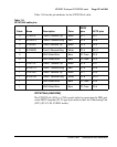
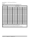
Table 116
DIP switch settings for NT5D97AA/AB (Part 2 of 2)
Card
Trunks
0 and 1
Port 0 Port 1 Trunk 0 Trunk 1