


NT8D02 and NTDK16 Digital Line cards Page 527 of 894
Circuit Card Description and Installation
Environmental specifications
Table 170 shows the environmental specifications of the card.
Connector pin assignments
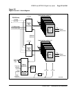
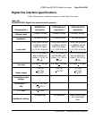
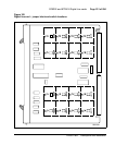
Table 171 shows the I/O pin designations at the backplane connector, which
is arranged as an 80-row by 2-column array of pins. Normally, these pin
positions are cabled to 50-pin connectors at the I/O panel in the rear of each
module for connection with 25-pair cables to the MDF.
The information in Table 171 is provided as a reference and diagnostic aid at
the backplane, since the cabling arrangement can vary at the I/O panel. See
Communication Server 1000M and Meridian 1: Large System Installation
and Configuration (553-3021-210) for cable pinout information for the I/O
panel.
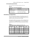
Table 170
Digital line card – environmental specifications
Parameter Specifications
Operating temperature 0° to +60° C (+32 to +140° F), ambient
Operating humidity 5 to 95% RH (non-condensing)
Storage temperature –40° to +70° C (–40° to +158° F)
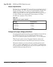
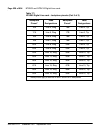
Table 171
NT8D02 Digital Line card – backplane pinouts (Part 1 of 2)
Backplane
Pinout*
Lead
Designations
Backplane
Pinout*
Lead
Designations
12A Line 0, Ring 12B Line 0, Tip
13A Line 1, Ring 13B Line 1, Tip
14A Line 2, Ring 14B Line 2, Tip
15A Line 3, Ring 15B Line 3, Tip
* These pinouts apply to both the NT8D37 and NT8D11 backplanes