


NT5D33 and NT5D34 Lineside E1 Interface cards Page 289 of 894
Circuit Card Description and Installation
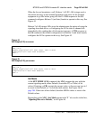
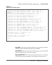
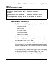
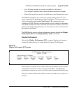
Figure 49
Display Configuration (D C) screen
Alarm operation and reporting
The MMI monitors the E1 link according to parameters established through
the Set Alarm command for the following conditions:
• Excessive bit error rate
• Frame slip errors
• Out of frame condition
• Loss of signal condition
• Blue alarm (AIS) condition
Descriptions of the excessive bit error rate and frame slip errors conditions
are found in “Configuring parameters” on page 278. Bit errors activate either
a level 1 or level 2 alarm. The remaining conditions, when detected, always
cause the system to activate a level 2 alarm.
An out-of-frame condition will be declared if 3 consecutive frame bits are in
error. If this condition occurs, the hardware immediately attempts to reframe.
During the reframe time, the E1 link is declared out-of-frame, and silence is
sent on all receive timeslots.
A loss of signal condition is declared if a full frame (255 bits) of consecutive
zeros has been detected at the receive inputs. If this condition occurs, the E1
link automatically attempts to resynchronize with the far-end. If this
condition lasts for more than two seconds, a level 2 alarm is declared, and
silence is sent on all receive timeslots. The alarm is cleared if, after two
LEI S/N 1103 Software Version 1.01 3/03/95 1:50
Alarms Enabled: YES Self Clearing Enabled: YES
Alarm Level 1 threshold value: E-7 Threshold duration (in
seconds): 10
Alarm Level 2 threshold value: E-5 Threshold duration (in
seconds): 1
Frame slips alarm level threshold: 5 Threshold duration (in hours
)
2
Current dip switch S1 settings (S1..S8) On Off Off On Off Off Off On
Current dip switch S2 settings (S1..S8) On Off On Off Off Off On Off