


NT7D16 Data Access card Page 499 of 894
Circuit Card Description and Installation
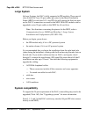
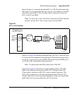
Figure 96 shows a connection through an RJ-11 or RJ-45 jack located at the
data station. It is recommended that four wires be used similarly to the AIM
drop when using the RJ-11 jack. Another cable is required to convert the
RJ-11 or RJ-45 into DB25.
Note: It is necessary to turn over Receive Data and Send Data between
the DAC and the AILU. This is done on the TN at the MDF.
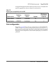
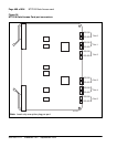
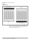
Figure 97 on page 500 illustrates the patch panel. RS-232-C cables are used
to connect the data equipment to the patch panel. This particular panel shows
two 50-pin connectors into twelve DB25. The signals from the MDF travel
on 25-pair cables, terminating at the patch panel.
Note: Use patch panels that follow the pinout of the DAC.
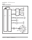
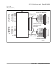
Figure 98 on page 501 describes an octopus cabling scheme. This cable
replaces the combined patch panel and RS-232-C cabling scheme. The
25-pair cable is split into six RS-232-C male or female connectors. This
allows direct connections to the data equipment from the I/O panel. The
octopus cable allows for the maximum segregation of the voice signals that
might otherwise be present within the same 25-pair cable.
Figure 96
RJ-11 or RJ-45 jacks
MDF
TxD
RxD
GND
DTR
EIA signals from
the DAC (unit n)
RJ-11
plug
1 (TxD)
6 (RxD)
5 (GND)
20 (DTR)
1 (TxD)
6 (RxD)
5 (GND)
20 (DTR)
6 (DSR)
8 (DCD)
4 (RTS)
5 (CTS)
RJ-11
jack
553-5023