


NT8D15 E&M Trunk card Page 629 of 894
Circuit Card Description and Installation
• monitor signals from the trunk interface and generate a message when
required for each state change
• control disabling and enabling of unit or card
• control A-Law and µ-Law operation modes
• control transmission pad settings
Maintenance features
The following features are provided for maintenance of the E&M trunk:
• indication of card status from self-test
• software enable and disable capability for individual units or entire card
• loopback of PCM signals to DS-30X for diagnostic purposes
• card ID for autoconfiguration and determination of serial number and
firmware level
Operation
The optional applications, features, and signaling arrangements for each unit
on the E&M trunk card are assigned through the Trunk Administration LD 14
and Trunk Route LD 16 programs.
Signaling and call control
The information in this section describes the signaling and call control of
E&M Type I and II trunks. The call is terminated and the trunk released by a
disconnect message sent to the associated unit.
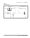
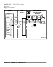
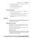
Figure 145 on page 630 shows the trunk signaling orientation for a tandem
connection between E&M and CO trunks.
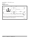
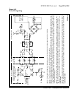
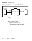
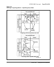
E&M Type I signaling
Figure 146 on page 631 shows E&M Type I signaling patterns for incoming
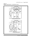
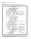
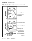
and outgoing calls. Figure 147 on page 632 shows Type I signaling patterns
on a tandem connection where the originating end is senderized and the route
is over a CO trunk (not applicable to CCSA).