


NT1R20 Off-Premise Station Analog Line card Page 163 of 894
Circuit Card Description and Installation
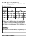
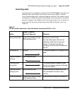
Port-to-port loss configuration
The loss plan for the NT1R20 OPS analog line card determines port-to-port
loss for connections between an OPS analog line card unit (port) and other
ports.
The transmission properties of each line unit are characterized by the OPS or
ONS class of service assigned in the Analog (500/2500-type) Telephone
Administration program LD 10.
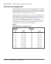
The OPS analog line card provides transmission loss switching for control of
end-to-end connection loss. Control of loss is a major element in controlling
transmission performance parameters such as received volume, echo, noise,
and crosstalk. The loss plan for the OPS analog line card determines
port-to-port loss for connections between an OPS analog line card unit (port)
and other IPE ports. LD 97 is used to configure systems for port-to-port loss.
See Software Input/Output: Administration (553-3001-311) for LD 97
service change instructions.
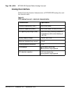
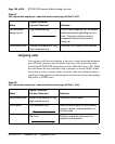
Electrical specifications
This section lists the electrical characteristics of the NT1R20 OPS analog line
card.
Circuit power
The +8.5 V dc input is regulated down to +5 V dc for use by the digital logic
circuits. All other power to the card is used by the line interface circuits.
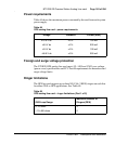
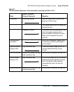
The ±15.0 V dc inputs to the card are used to power the analog circuits. The
+5 V dc from the module power supply is used for the analog hybrid. The
–48.0 V dc input is for the telephone battery. Ringing power for telephones is
86 Vrms ac at 20 Hz on –48 V dc. The Rsync signal is used to switch the
20 Hz ringing on and off at the zero cross-over point to lengthen the life of
the switching circuits.