


3 - 6
3 DESIGN
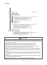
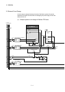
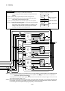
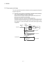
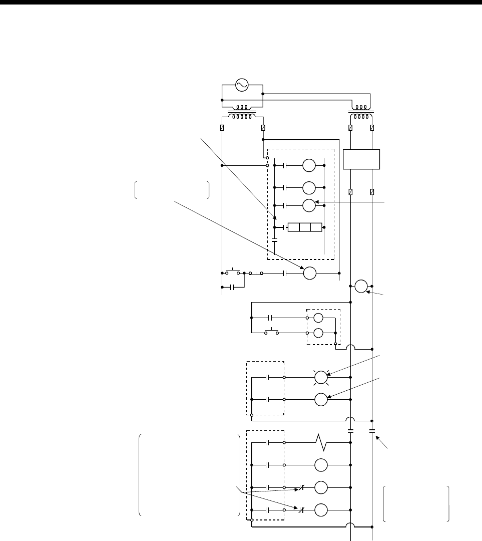
(2) System design circuit example of the PLC CPU area
interlocked with RA1
(run monitor relay)
RUN/STOP circuit
Power to output
equipment switched
OFF when the STOP
signal is given.
START SW
STOP SW
MC
RA1
MC
RA2
XM
L
Ym
Yn
Output module
MC2
MC1
MC1
RA1
M10
Program
PLC CPU area
Transformer
Fuse
Power supply
MC2
MC
Ym
SM52
SM403
TM
XM
MC1 N0 M10
TM
Input switched when
power supply established
ON when run
by SM403
Low battery alarm
(Lamp or buzzer)
Voltage relay is
recommended
Set time for
DC power
supply to be
established
(-) ( )
Yn
DC power
RA2
Transformer
Fuse
Fuse
Output module
MC
Interlock circuits as necessary.
Provide external interlock
circuits for conflicting
operations, such as forward
rotation and reverse rotation,
and for parts that could
damage the machine or cause
accidents if no interlock were
used.
N0
In the case of an
emergency stop or
a stop caused by
a limit switch.
+
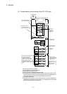
The start-up procedure is as follows
1) Switch the Motion controller power ON.
2) Set the Motion controller to RUN.
3) When DC power is established, RA2 goes ON.
4) Timer (TM) times out after the DC power reaches 100[%]. (The TM set value
should be the period of time from when RA2 goes ON to the establishment of
100[%] DC voltage. Set this value to approximately 0.5 seconds.)
5) Turn ON the start switch.
6) When the electromagnetic contactor (MC) comes on, the output equipment is
powered and may be driven by the program. (If a voltage relay is used at RA2,
no timer (TM) is required in the program.)