


APP - 23
A
PPENDICES
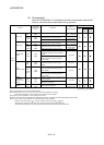
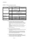
APPENDIX 1.7 Differences of CPU display and I/O assignment
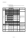
Table 1.7 Differences of CPU display and I/O assignment
Item Q170MCPU Q173DCPU/Q172DCPU
CPU display
• Motion CPU area : Q170MCPU-PCPU
• PLC CPU area : Q170MCPU-SCPU
• Motion CPU : Q173DCPU, Q172DCPU
• PLC CPU : Q06UDHCPU, etc.
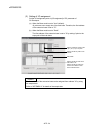
Base mode
(Auto)
• The main base of eight slots corresponding is built
into the Q170MCPU.
• 16 points are set to each empty slot.
• First address of the extension base is "70".
• The main base and extension base are
automatically determined.
• I/O or empty slot, etc. is automatic determined,
and the points are assigned.
I/O assignment
setting
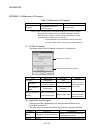
Base mode
(Detail)
• I/O assignment points are individually assigned.
When the first address of the extension base is
set to address "0", the setting is as follows.
• Main base: 8 slots
• Number of points of each empty slot: 0 point
• I/O assignment points are individually assigned.
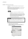
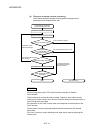
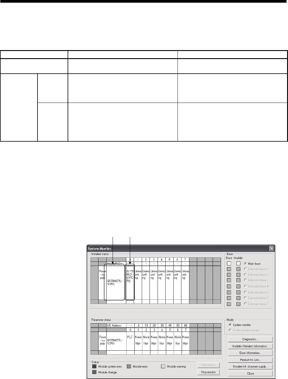
The CPU display and setting of I/O assignment are shown below.
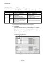
(1) CPU display
Confirm the CPU display of the PLC CPU area and Motion CPU area on the
System Monitor screen displayed on [Diagnostics] – [System monitor] of
GX Developer.
PLC CPU area is displayed as "Q170MCPU-SCPU", and Motion CPU area is
displayed as "Q170MCPU-PCPU".
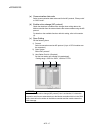
PLC CPU area
(Q170MCPU-SCPU)
Motion CPU area
(Q170MCPU-PCPU)